Creating a New Drawing
In this Task
- A rectangle will be drawn to a specific size by inputting the Width and Height values into the data fields.
- Corners of the rectangle will be blended using a Fillet radius.
associated tasks
- Using the Zoom tools.
- Different fillet radii will be used in this task. Always input the new value into the Radius field.
before you start
- You may refer to the [sample drawing](https://www.tricad.co.za/2020-1/SharkCAD/Content/Resources/Drawings/Session 1 Sketch%26Model.sfx) for this task. More…The sample drawing for this session contains the 2D Sketch and the 3D Model. Frequently, these 2 layers are superimposed. Use the Concept Explorer to control the display of the layers. Create your own layers if you wish to produce the design from scratch or pan to an unused area of the editor.
- Follow the instructions below under the heading New Drawing using the Wizard to start a new drawing.
- Create a custom drawing using millimeter units.
- Use a landscape sheet approximately A4 size.
- Use an Engineering Drawing Scale at 1:1 (full scale)
- Use an Iso Dimension Format.
take note
- The new rectangle will automatically be drawn on the current layer. Use the Concept Explorer to assign a layer as current.
- The resulting arc of the blend will be created as a separate drawing object, connected by its endpoints to the associated lines.
New Drawing using the Wizard
New drawings can be created using the setup wizard. This allows a custom drawing to be created by suggesting standard settings, units of measurements and page layouts.
Each new drawing which is created using the Wizard contains layers which can either be used in their original format, or changed to suit the user.
In this task, a simple A3 landscape drawing will be created, using millimeter units.
Select File > New from Wizard and select a Custom Drawing layout. Click Next.
Select a Unit Format of millimeters, Click Next.
Set the Printer Paper Size to Landscape. The width and height area is not important at this stage. Click Next.
Set the Drawing Scale to Engineering and the scale to 1:1 (Full Scale). Click Next.
Create Annotation settings to Text Height = 5 and Page Output to 5. Set the dimension format to either ANSI or ISO depending on your region or preference. Check the option to Scale Dimension Values with Text Height. Click Finish.
concept Explorer | Layers
Window | Concept Explorer
The Concept Explorer is a utilities manager which allows control over object properties such as layer, color, linetype etc. It also provides a selection of symbols which can be conveniently inserted by dragging into the editor.
New layers are created so that specific object properties such as color, visibility etc, can be more easily controlled.
When a new layer is created and activated as the current layer, all subsequent objects drawn in the editor will automatically be drawn on this layer.
Objects which were previously drawn on another layer can be moved to a new layer using the Inspector.
From the Windows menu, open the Concept Explorer, making sure the Layers tab is active. The layers shown below are default layers which are automatically created when a new drawing is started using the Wizard.
From the image below, notice that the Layer1 box is shown activated by the pencil icon and shown by the pointer. Layer1 is activated as the current layer, and all subsequent objects will be drawn on Layer1.
All layers have a color wheel to the right of the layer name. This indicates that the color of the layer can be changed at any stage of the design. When a color is fixed instead of the color wheel, the color of the layer is locked to the selected color, and objects drawn on Layer1 can only be viewed in the set color.

Layer Control using the Content Explorer.
Layer1 is the current layer
Rectangle with Single Lines

Draw > Polygon > Diagonal Polygon
This sketch tool creates a 4 sided polygonal shape by inputting the Width and Height values.
The Rectangle draws from a corner to an opposing corner.
The Rectangle can either be drawn as a Single Line polygon, consisting of 4 separate but connected lines or as a Smart Polygon.
The Smart Polygon is a single object.
Options Include :
Center Point Polygon
Diagonal Polygon
Three Point Polygon
Major Axis Polygon
Select the Rectangle tool from the toolbar or use Draw > Polygon > Diagonal Polygon.
Make sure the option shown in the upper left corner of the status bar is set to Diagonal Polygon, shown below.

Make sure the Single Line option is selected, shown below.

Left click a position in the edtor which would represent the lower left corner of the Rectangle, then use the TAB keyboard key to access the Width field. Input 50.
Use the TAB keyboard key to move to the Height field. Input 40, then press enter. Press they keyboard Esc key to discontinue the command or right click in the editor and find deselect.
The Rectangle has drawn as 4 single but connected lines, shown below.
 `
`
Single Line Rectangle
Right click in the editor and select Zoom All, then use the mouse scroll wheel to reduce the zoom so that all objects are visible in the editor.
Fillet Two Lines

Modify > Fillet > Fillet Two Lines
The Fillet tool creates an arc or radius between 2 lines, circles or arcs to a specific radius.
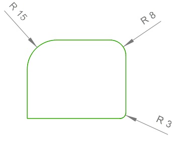
Fillet blends will be applied to 3 corners shown in the illustration at the end of this task.
Select the Fillet Two Lines tool from the toolbar or use Modify > Fillet > Fillet Two Lines.
Use the keyboard TAB key to access the Radius field, then input 15.
Select the 2 points on the line shown in the illustration below.

Selecting diagonal points for the fillet
The result is shown below.
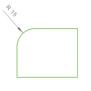
Fillet of 15 created
TAB to the Radius field and input 8, then select the points on the lines shown below.

Selecting diagonal points for the second fillet
Repeat this for the lower right corners, creating a radius of 3, below.
Right click and select DeSelect to discontinue the command.