Part 2 Layer Control
In this Task
- The layers which contain the sketch and model of Parts 1, 3, 4 and 5 will be deactivated at the top level.
- The sketch profile will be extruded.
- The WorkPlane will be moved to the quadrant of the arc.
Associated Tasks
- Using Transparency mode.
- Using Wireframe visual mode.
Before you
-
Part 2 will be drawn in the same drawing as the previous Session, or you may use the [sample drawing](https://www.tricad.co.za/2020-1/SharkCAD/Content/Resources/Drawings/Parts_Assembly._Part 2.sfx) for this Task.
-
Use the Concept Explorer to deactivate any top-level layers for Part 1 . Only the sketch for Part 2 should be visible in the editor.
-
View is set to Isometric.
Take Note
- The WorkPlane can only be snapped to an object if the WorkPlane snap is enabled. Use Window > Snaps to check that the WorkPlane snap is activated.

Part 2 | Model Layer
Open the Concept Explorer and activate as current the Model layer for Part 2. The Layers for Parts 1, 3, 4 and 5 are deactivated at top level, shown below.
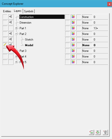
Activating Part 2-Model layer| Layers for Parts 1, 3, 4 and 5 deactivated at top level
Extrude Solid

Modify | Draw | Solid from Curves | Extrude Solid
A closed profile can be extruded by providing a positive or negative distance from the sketch.
Select the Extrude****Solid tool from the toolbar or use Modify | Draw | Solid from Curves | Extrude Solid.
TAB to the Distance field and input a value of 12. Make sure the option is set to Distance.
Use a pick window to select all the objects. The result is shown below.
The Inspector
Window > Inspector
The geometrical and spatial information, as well as the properties (layer, color, line style etc) for any curve or solid can be found using the Inspector.
In the illustration below, the color has been changed to Tangerine. Select Part 2, then double click onto the same part to display the Inspector. Select the Properties option shown by Point 1 below. Select the Color option shown by Point 3, then select the color shown by Point 3.
The result is shown below.

Using the Inspector to change the color of Part 2
WorkPlanes
WorkPlane
The WorkPlane is a coordinate work surface which defines the orientation of the XYZ axes and is used to precisely position objects in 3-dimensional space.
The WorkPlane is represented by a 3-directional arrow representing the X, Y and Z axes.
The WorkPlane responds in accordance to the view, with the XY axes lying in a parallel plane and the Z axis lying in a perpendicular plane to the view.
The WorkPlane can be offset, moved and manipulated using the XYZ rotation arrows and user-created WorkPlanes can be used for specific work surfaces.
Displaying the WorkPlane
WorkPlane | Show WorkPlane
By displaying the WorkPlane, the axis is displayed in the editor, providing a visual indication of the XYZ coordinate directions.
Position the cursor over the extrusion, right click, then select Transparency option.
From the WorkPlane menu, select Show WorkPlane. The WorkPlane should be displayed in the editor similar to the illustration below, although it may be necessary to use the Zoom tools to display the WorkPlane and model in the current window.
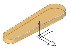
WorkPlane axes displayed
Moving the WorkPlane
The WorkPlane itself is an object, allowing rotation thru its axes and movement from its origin point. The origin point is at the XYZ intersection point shown below.
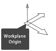
WorkPlane origin at intersection of XYZ axes
The WorkPlane can be moved from the intersection of the XYZ axes shown above to another point in the editor. Select the origin of the WorkPlane and move it to the quadrant point of the bottom arc shown below.

WorkPlane placed on quadrant of bottom arc
Always view the model from another viewpoint to check the location of the WorkPlane. In the illustration below, the WorkPlane origin can be seen in Wireframe visual mode using Front view.
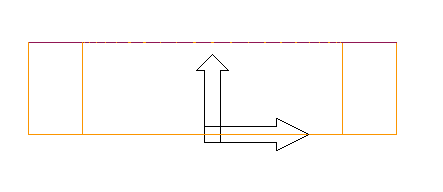
WorkPlane shown from Left Side view, Wireframe mode
center point circle

Draw | Circle | Center Point Circle
This circle tool allows the input of the circle diameter prior to inserting the circle.
The center of the circle is then provided.
View is set to Isometric. Select the Center Point Circle tool from the toolbar or use Draw > Circle > Center Point Circle.
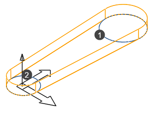
Find the center point, then left click when the center snap is displayed. TAB to the Diameter field and input 48. This is shown by circle 1 below
Repeat this, inserting a circle with a radius of 34, shown as circle 2**,** onto the opposite end, shown below.