Adding New Sketch Objects
In this Task
- New parts will be created by drawing their profiles on points referenced by the original sketch geometry.
- The new sketch objects will be extruded.
- The volumes of the 3 parts will be combined.
Associated Tasks
- Center Point Circle.
- Transparency Mode.
- Continual Dynamic Rotate.
- Add Solid.
Before you Start
- Model is viewed in Isometric view.
Take Note
- Points on a sketch can be projected in any plane. Make sure the correct plane is projected when locating a center.
- Some views in the illustrations below are rotated for illustrative clarity. Should you wish to rotate view to reflect the view shown in the illustrations, use View > Rotate View.
- The color of the part has been changed to Cyan to illustrate the newly inserted parts.
When new sketch geometry is inserted onto a part, the geometry of the existing part can be useful for placing the new sketch objects.
In order to see the original sketch geometry as well as the 3D part, the Transparency mode is used.
Transparency
Right click in Editor | Transparency
This visual display mode displays a part as transparent, allowing all edges, facts and vertices to be easily viewed.
One part at a time can be displayed as transparent, which is useful when assembling objects.
Position the cursor over the part, then right click and activate the Transparency option. The result, shown below, provides a display of the sketch geometry and the facets, edges and vertices of the model.
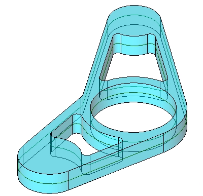
Transparency mode shows sketch geometry, including facets and vertices of the extrusion
Center Point Circle

Draw | Circle | Center Point Circle
This circle tool draws a single circle by defining the center point and diameter.
The diameter can either be defined by selecting a point in the graphics editor, or by inputting a value into the Diameter field.
The diameter of the circle can be changed after insertion by changing the value in the Diameter edit field.
The center point of the arc of the sketch geometry shown below will be used to seat the new circle. The quadrant of the outer arc will be targeted, allowing the X-Y-Z alignment to track to the center of the arc, using the same plane.
Select the Center Point Circle from the toolbar or use Draw | Circle | Center Point Circle. Target (without left clicking) the quadrant of the arc, shown below.
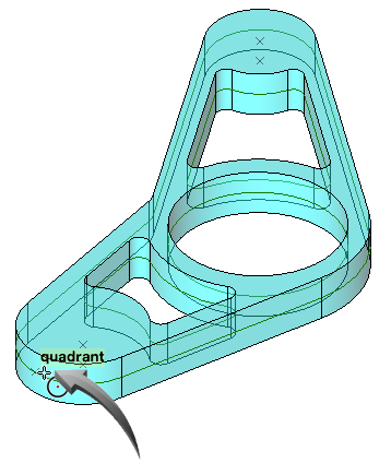
Finding the quadrant of the arc – illustration rotated for clarity
Allow the XYZ alignment LogiCursor to move along this axis, shown be by arrow below. Do not left click.
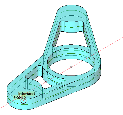
Using the LogiCursor to track along an alignment from the quadrant – illustration rotated for clarity
Move the cursor slightly until the Center of the arc is found, shown below. Left click only when the Center magnetic point is shown, below.
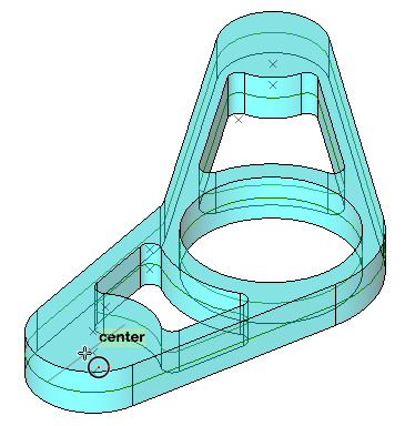
Finding the center on the midplane – illustration rotated for clarity
TAB to the Diameter field and input 60. The result is shown below.
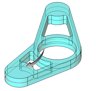
Circle with diameter 60 placed on midplane – illustration rotated for clarity
Rotate View
View | Rotate View
This visual tool rotates a view in isometric view to the opposite side.
From the View menu select View > Rotate View. The isometric view is rotated through 180° so that the opposite angle of the view is presented, shown below.
Insert a new circle using the method above to insert a new circle with a diameter of 50.
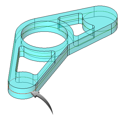
Isometric view rotated
Extrude Solid

Draw | Solid from Curves | Extrude Solid
This extrusion tool sweeps a 2D profile in a plane perpendicular to the WorkPlane to create a 3D object.
A bi-directional extrusion can be created which creates an equidistant above and below WorkPlane extrusion.
Closed profiles only can be extruded.
When closed objects within the profile are selected as part of the profile, the volume of the extruded inner objects will be subtracted from the primary solid.
The two newly inserted circles can be selected together and extruded to a midplane height of 40.
Hold down the SHIFT key, then select both circle profiles, shown below.
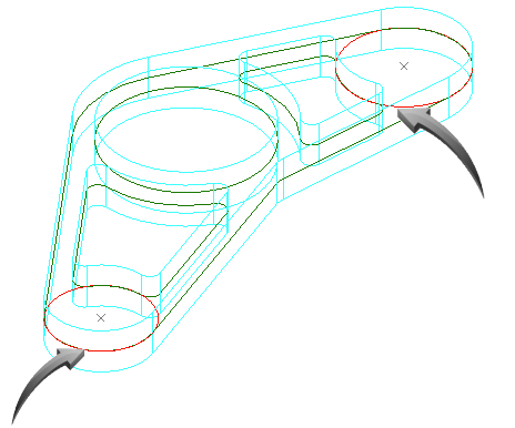
Selecting both circle profiles using the SHIFT key
Select the Extrude Solid tool and TAB to the Distance field and input 40. Make sure the Midplane option is still activated.
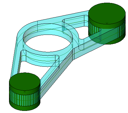
Circles extruded to midplane height of 40
Add Solid

Modify | Solid Booleans | Add Solid
This 3D boolean function combines the volume of 2 intersecting or adjoining 3D solids or surfaces.
The three separate parts will now be combined into a single unit. Select the Add Solid tool from the toolbar or use Modify > Solid Booleans > Add Solid.
Select the main part first, then either of the cylindrical extrusions. The result is shown below.
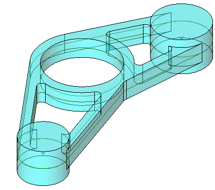
Parts combined into single unit | View rotated using View > Rotate, Zoom All
Please Note
When the circles were selected for extrusion, they were selected together. This forced them to be extruded as a single object. Combining the parts only required the selection of the main part and one of the cylinders.
Additional Resources
In addition to the Rotate View tool used above, the Dynamic Rotate tool can be used.
Dynamic Rotate (continual)

The Dynamic Rotate tool can be used to perpetually rotate the view of the model around an axis until a convenient view is found.
To rotate the object around an axis using perpetual motion, double click onto the Dynamic Rotate icon, shown above.
