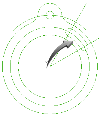
Alignment Angles
In this Task
- Diagonal lines at 30 and 60 degrees will be drawn from the center of the largest circle.
- Circles will be inserted on the intersections created by the arc and the new angled lines.
- The arc will be offset to create the curved edges of a slot.
- The arcs will be trimmed.
Associated Tasks
- Creating an alignment angle.
- Center Point Circles.
- Offset.
- Trim.
Before you Start
- Accurate placement of sketch geometry is important. Make sure snaps are enabled using Window > Snaps > Enable.
Take Note
- Alignment angles allow the cursor to track to angles specified in preferences.
- When drawing lines which track to angles, take care to track to the correct angle.
- When drawing a line, both the length and the angle can be viewed in the edit fields at the top of the editor.
Creating a curved slot using Alignment Angles
Preferences | Alignment Angles
A line will automatically track to the angles input into the Alignment Angles snap field.
The cursor can be forced to track automatically at specific angles. This is done by creating an Alignment Angle in the Preferences > Snaps dialog box, shown below.
Select Preferences > Snaps, then input 30, 60 into the Alignment angle field, separated by a comma. It is not necessary to input the degree symbol.
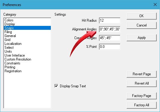
Creating alignment angles of 30 and 60 degrees
Select the Line tool from the toolbar or use Draw > Line.
Start the line from the center of the circle, shown below, then drag the cursor outwards, allowing the angle to track at 30°, shown below.
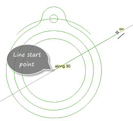
Line tracking along a 30° angle
Repeat this by starting another line at the center of the circle, then allow this angle to track to 60°, shown below,

Line tracking along a 60° angle
The result is shown below.

Lines created at 30 and 60 degrees from circle center
Center Point Circle

Draw | Circle | Center Point Circle
This circle tool draws a single circle by defining the center point and diameter.
The diameter can either be defined by selecting a point in the graphics editor, or by inputting a value into the Diameter field.
The diameter of the circle can be changed after insertion by changing the value in the Diameter edit field.
Select the Center Point Circle tool, then insert 2 circles with diameters of 10 onto the newly created intersections, shown below. Take care to snap the center of the circles onto the intersection.
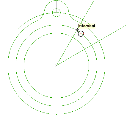
Finding the intersection for the new circle center
The result is shown below.
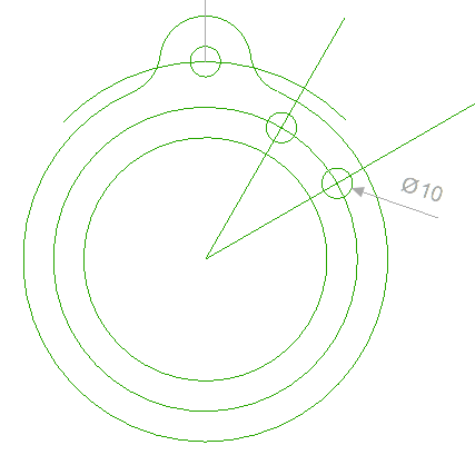
Circles with diameters of 10 placed on the intersections
Offset Curve

Modify | Trim | Offset Curve
This duplication tool creates an offset of an existing line, arc or circle to a specified distance.
Options :
Offset to Value
Offset by Point
Offset Face Edges
A curve or line can be offset to a specific value. In this following task, the circle which intersects the centers of the new circles will be offset to a value of 5 either side of the circle, shown below.
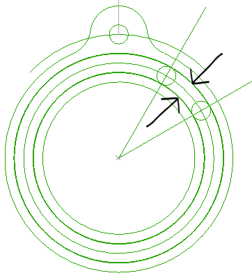
Center arc will be offset by 5 either side
Select the Offset tool from the toolbar or use Modify > Trim > Offset Curve.
TAB to the Offset field and input 5. Select the circle with passes through the center of the smaller circles, then left click to the right of the circle, shown below.
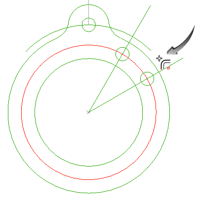
Offsetting to the right of the selected arc
Repeat this, by selecting a point to the left of the selected circle, shown below.

Offsetting to the left of the selected arc
The result is shown below.

Trim

Modify | Trim | Trim
The Trim tool trims lines, arcs of circles to a defined boundary edge.
The keyboard SHIFT key is used to select multiple objects and can be used to add or remove objects to the selection.
Select the Trim tool from the toolbar or use Modify > Trim > Trim
Hold down the keyboard SHIFT key, then select both smaller circles and the circles to which they are tangential, shown below.
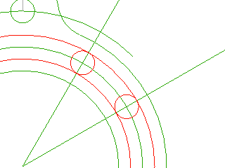
Selecting the boundary edges for the trim
Release the SHIFT key, then trim the arc segments using similar positions to those shown below. Note : It may not be necessary to trim points 3 and 4 after the Trim has been used at points 3 and 4.
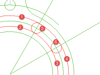
Trimming the segments
A curved slot has been created, shown below.