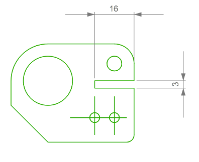
Creating the Slot
In this Task
- A non-regular polygonal shape will be drawn to represent a slot.
- A radius of 0 will be given to create 90° corners.
- The top of the slot is aligned to the center of the large circle. A start point for the rectangle will be provided using the LogiCursor to project a point from the center of the larger circle.
Associated Tasks
- Using the LogiCursor to create a projected point.
- Using a Pick Window Selection
- Trimming a segment.
Before you Start
- Snaps are enabled. Use Window > Snaps to check all snaps are enabled, particularly the XYZ alignment snap.
Take Note
- The LogiCursor creates alignment with a projected point. Left click only when the alignment lines is displayed when drawing to projected points.
[ ](https://www.tricad.co.za/2020-1/SharkCAD/Videos/2d-01-09 sketch.mp4 "Internet Connection Required")
Rounded Rectangle

Draw | Polygon | Rounded Rectangle
This rectangle tool is useful for drawing a rectangle by identifying diagonal points.
A radius can be given to create a rectangle with rounded corners, but a radius of zero creates a 4 sided non-regular polygonal shape.
Select the Rounded Rectangle tool shown above or use Draw > Polygon > Rounded Rectangle. Select the Single Line option from the Edit bar.
Allow the cursor to track to the center of the circle, shown by the arrow below, do not left click.
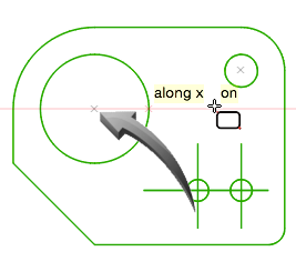
Aligning the top of the rectangle to the center of the circle
Drag the cursor to the projected orthogonal point on the right vertical edge, shown by the arrow below.

Projecting the start point from the center to the vertical edge
Left click to start the upper right corner of the rectangle, then use the keyboard TAB key to input a Width of -16. Use the TAB key to input a Height of -3. TAB to the radius field and input 0. The result is shown below.
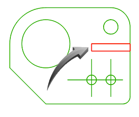
Slot created with top aligned to center of circle
Using a Pick Window Selection
Left-to-Right Selection
In this task, the right edge of the new rectangle should be deleted. By using a left-to-right windows selection, only objects which fall within the selection rectangle are selected. In this case, the endpoints of the main vertical edge fall outside the selection rectangle and will not be selected.
Using the Select tool from the toolbar, drag the cursor around the right edge of the newly created rectangle which forms the slot, shown below. Take care to only use a left-to-right direction.
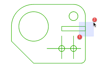
By creating a left-to-right pick window, only the vertical edge of the new rectangle is selected, shown below.
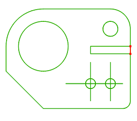
When the vertical edge is selected, shown above, use the keyboard Delete key to delete this object. Please note, the line which represents the main right edge will still be visible.
Trim

Modify | Trim | Trim
The Trim tool trims lines, arcs of circles to a defined boundary edge.
The keyboard SHIFT key is used to select multiple objects and can be used to add or remove objects to the selection.
The Trim tool will be used to trim the segment of vertical line shown below.
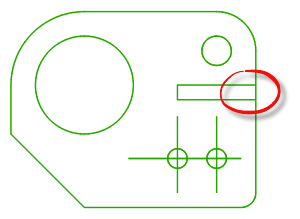
Vertical segment to be trimmed
Select the Trim tool from the toolbar or use Modify > Trim > Trim.
Use a left-to-right window selection shown below to select the remaining edges of the small rectangle as the boundary edges of the trim.
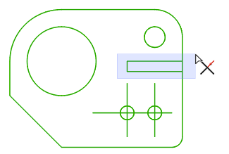
When the 3 edges are selected (shown in red) click the segment between the vertical lines, shown below. Right click in the editor and select DeSelect to exit from this command.
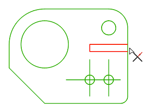
The result is shown below. Dimensions are shown for illustrative clarity only.