Creating the Cylinders
In this Task
- The newly drawn circles will be extruded upwards to form cylindrical shapes.
- These volumes of the cylinders and arm will be combined.
- Holes with a diameter of 16 will be drilled from the top face to the bottom.
Associated Tasks
- Extrude
- Add Solid
- Hole Feature
Before you Start
- View is in Isometric or Trimetric view.
- Transparency mode is enabled.
Take Note
- When selecting both circles for extrusion, the resulting extrusion will form a single unit.
- Save the drawing at the end of this Task.

Extrude Solid

Modify | Draw | Solid from Curves | Extrude Solid
A closed profile can be extruded by providing a distance above or below the WorkPlane.
Select the Extrude Solid tool from the toolbar or use Modify | Draw | Solid from Curves | Extrude Solid, making sure the Distance option is selected.
TAB to the Distance field and input 25. Hold down the SHIFT key and select both circles. The result is shown below.
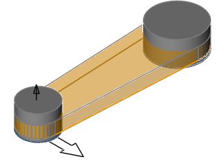
Both circles extruded as a single unit
Add Solid

Modify | Solid Booleans | Add Solid
This 3D boolean function combines the volume of 2 intersecting or adjoining 3D solids or surfaces.
Select Add Solid from the toolbar or use Modify > Solid Booleans > Add Solid. Add the volumes of the cylinders to the primary solid so that the result is similar to the illustration below.
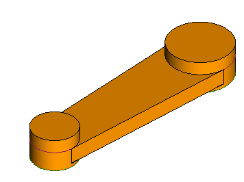
Volumes of units combined using Add Solid
Hole Feature

Modify | Solid Feature | Hole Feature
This tool allows the creation of a predefined hole which automatically subtracts the hole material from a solid.
This tool is useful for creating a hollow extrusion through a solid by penetrating the depth of the solid.
Two holes of diameters 16 will be inserted onto the centers of the cylinders. The hole will extrude through the combined volume of the cylinder and the arm.
Select the Hole Feature from the toolbar or use Modify > Solid Feature > Hole Feature making sure the Through option is selected. TAB to the edit fields and input a Diameter of 16 and a Depth of 25.
Select the top of the first circle shown below, making sure the Center is found.
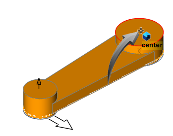
Finding the center on the top face
Repeat this for the second cylinder using the same diameter. The result is shown below in transparency mode and rotated view.

Holes shown extruding through combined units
At this stage of the project, 2 parts have been created in the editor, shown below. The layer structure is displayed, showing the layer visibility for Parts 1 and 2.
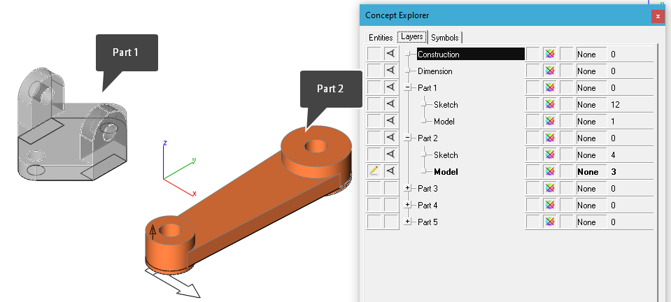
Parts 1 and 2 with their layer visibility structure shown in the Concept Explorer
Save the drawing at the end of this Task.
Drawing Layout and Printing
Should you wish to print your drawing at this stage, please refer to Drawing View Layouts and Printing.
