Modifying the Part
In this Task
- The solid will be modified by adding new objects and removing faces.
Associated Tasks
- Remove Face.
- Add Hole
- Dynamic Rotate
Before you Start
- The Ambiguity popup is enabled in order to distinguish between adjacent faces. This is enabled using Preferences > Select > Enable Ambiguity Popup.
Take Note
- This drawing should be saved at the end of this task.
Modifying the Solid
Solid objects can be modified after construction using a variety of tools. For examples, solid models can be modified using some of the methods below.
- by creating new sketch profiles on their facets and building extrusions which add new parts to the model.
- adding objects such as a blend, chamfer, hole or boss.
- by modifying the faces of the solid using offset face, draft face, remove face etc.
In this task, the following tools will be used to modify the solid.
- Dynamically rotating the part.
- Removing the chamfer and the larger blend using the Remove Face tool.
- Adding a new hole which is aligned to the two existing holes.
Dynamic Rotate

This visual tool revolves the sketch or model by moving the view about a default axis.
By double-clicking onto the Dynamic Rotate tool, the view will rotate continuously. The rotating motion can be stopped by left-clicking the editor.
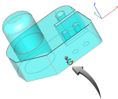
In the example below, the solid is being rotated about a point indicated by the arrow. The colors of the rotation handle relate to the colors of the axis, shown at the top right of the object.
To dynamically rotate a part in order to make a face more accessible, select the Dynamic Rotate tool then left-click-hold and rotate the view until the face is exposed for modification.
Remove Face

Modify | Solid Direct Edit | Remove Face
This modification tool removes the face of a solid by extending the neighboring faces to replace the removed face.
When removing a face which is constructed from a chamfered or blended edge, the neighboring faces will be extended to create a 90° corner.
In this task, the solid will be modified by removing the faces which were created by the blend and the chamfer of the original sketch profile, shown below.
Use the Rotate ViewView | Rotate View or Dynamic View so that the chamfered edge is visible, shown below.
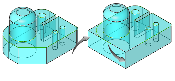
Blended and Chamfered edges removed – view rotated for illustrative clarity
Select the Remove Face tool from the toolbar or use Modify | Solid Direct Edit| Remove Face.
Select the chamfered edge, taking care to use the popup to select the correct face, shown below.
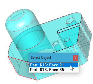
Selecting the face for removal | – view rotated for illustrative clarity
Select the correct face to remove. The result is shown below.

Face removed from solid – view rotated for illustrative clarity
Right click in the editor and select Dynamic Rotate. Use the mouse cursor to rotate the model slightly so that the blended edge is visible, similar to the illustration below.
Select the face to remove, taking care to select the highlighted face only, shown below.

Selecting the face for removal
The result should be similar to the illustration below after returning to Isometric view.
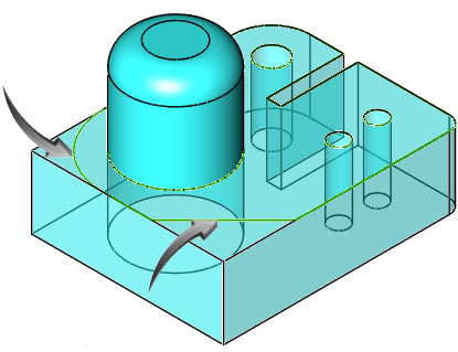
Faces removed, sketch geometry retained. Shown in Isometric view.
Isometric View
To return the model to a standard view, right click in editor and select Isometric or Trimetric view. The model will be aligned to the selected view at the same zoom magnification.
Hole Feature

Modify | Solid Feature | Hole Feature
This tool allows the creation of a predefined hole which automatically subtracts the hole material from a solid.
Options include :
- Counter Bore
- Counter Sink
In this task, the hole will be aligned with the edge of the cylindrical extrusion and the center of the neighboring hole, shown by the pointer below.

Position for insertion of new hole
In this example, a simple hole will be inserted on the top face of the solid. The depth of the solid is 15. The diameter of the hole is 4.
Right click in the editor and select View > Top View so that the view similar to the illustration above is displayed.
Select the Hole tool from the toolbar or use Modify> Solid Feature> Hole Feature. Make sure the option is set to Simple Hole.
TAB t the edit fields and input a depth of 15 and a diameter of 4.
Select the top face of the solid, taking care to use the popup to select the correct face, shown below.

Align the center of the hole with the center of the smaller circles and the right quadrant of the cylinder, shown below.

Finding the position for the hole
When an intersection is shown by the two projected guidelines, left click to define the position of the hole. The result is shown below from the top and isometric views.

New hole added
Use these tools to create your own model. In the example below, the [Blend Edge](3D Session 01_03.htm#Blend) tool was used to recreate the blended edge using a radius of 15. The Chamfer Edge tool (alongside the Blend Edge tool in the toolbar menu) was used to recreate the chamfered edge using a distance of 15.
The result is shown below. In the example below, the transparency option was removed. Position the cursor over the model, right click and uncheck the Transparency option.
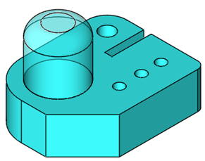
Model shown in isometric view with Transparency off
Drawing Layout and Printing
Should you wish to print your drawing at this stage, please refer to Drawing View Layouts and Printing.
